

|
Flexible heaters is a product family that generically describes thin and flexible heating elements that can be attached to various objects to provide freeze protection, consistent temperatures, and thermal control from -80C to +230C and higher. Original equipment manufacturers and after-market installers should recognize, however, that these flexible heaters are sub-divided into two primary technology platforms: etched-foil and wire-based technology. The most common technology and industry veteran is wire (wire strands woven together or single strand wire) laminated within nylon reinforced silicone rubber. These types of heaters are typically .032” thick and are used throughout many industries to attach against piping, portable drums, food warming equipment, and a host of applications, including many outdoor uses due to silicone rubber’s excellent water resistance properties. Alternatively, etched foil heaters are a relatively new technology (developed in the last 40 years) and are used in more advanced thermal management applications and/or limited thickness installations.
The basic design principles to arrive at the desired thermal performance of flexible heaters are essentially the same between etched foil and 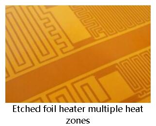 wound wire. Both utilize various resistive metals with differing resistivity characteristics. In designing a heater to a specific wattage level, manufacturers of both types of heater technologies have the option to incorporate combinations of alloys, diameters of wire (or cross sectional area), and overall length of the element to meet the customer’s defined total resistance and correlating wattage output based upon the voltage applied. There typically is not one single combination that will meet the requirement – the manufacturer of the flexible heater will select the blend of the variables that produces the most cost effective solution that meets the thermal and mechanical characteristics defined by the customer. wound wire. Both utilize various resistive metals with differing resistivity characteristics. In designing a heater to a specific wattage level, manufacturers of both types of heater technologies have the option to incorporate combinations of alloys, diameters of wire (or cross sectional area), and overall length of the element to meet the customer’s defined total resistance and correlating wattage output based upon the voltage applied. There typically is not one single combination that will meet the requirement – the manufacturer of the flexible heater will select the blend of the variables that produces the most cost effective solution that meets the thermal and mechanical characteristics defined by the customer.
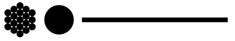 Equivalent cross sectional areas of 19 strand .003” dia wire, solid wire, and .002” thick foil. Just like their wound wire counterparts, designers of etched foil heaters seek to arrive at an overall resistance of the single conductive element routing through the heater shape. The above diagram shows a visual ratio of the size of a resistive wire compared to the same cross sectional area of a foil element. This is an example of a braided wire comprised of .003” strands and the relative size of an equivalent solid wire and the width of an equivalent etched foil conductor. This translates into about a 5 to 1 ratio between the overall wire diameter and the etched foil element width when using .002” foil of identical alloy. 
Etched Foil Advantages.
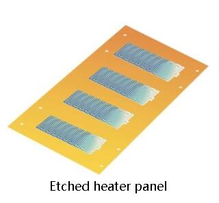
Etched foil heater technology integrated into miniature heaters
Etched foil patterns, despite needing wider widths to accomplish equivalent resistance of a wire, actually permit a much tighter patterning of elements. With etched foil technology, the fabrication processes provide tight spacing control and prohibit a conductive element from coming in contact with an adjacent element. This control enables spacing between elements to be as tight as .004” which is not permissible with wire technology. This precise patterning capability translates into even thermal distribution – one of the driving reasons designers utilize etched foil heaters. Additionally, since the element pattern is photo-lithography processed, precise repeatability of the heating element is provided.
The thermal control and thermal precision of etched foil heaters is also due to the large surface area of the etched element. Compared to wire where heat is transferred via a tangent point or an arc area of the circular element, the flat surface area of an etched element provides uniform and significantly more surface for the heat to transfer to the mating heat sink effectively and efficiently. Wire-based heaters typically need to run hotter to make up for this difference. Other reasons to utilize etched foil heaters include the overall thickness of the heater package. Etched foil heaters can be produced with thinner materials such as polyimide (DuPont Kapton® for example), enabling etched foil heaters to be produced with an overall thickness of .005” compared to traditional silicone rubber wound wire heaters at .032” thick or more. This thickness advantage is highlighted by etched foil’s ability to provide heating in a small packages and around tight bend radius mounting surfaces. 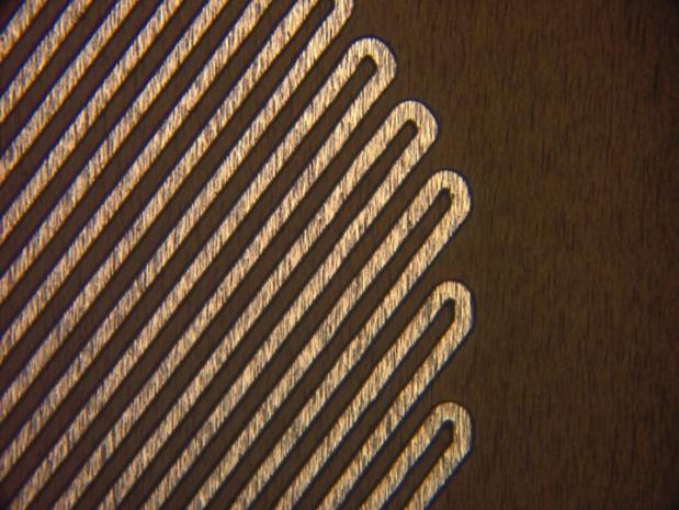 Ultra fine element widths and spacing is possible with etched foil heaters. Shown here are .003” wide elements with .003”spacing. Another valuable aspect of etched foil technology is that these types of heaters can easily incorporate components because the devices can be soldered directly to the heater foil using traditional soldering technologies. Not only does this type of design permit adding of single components such as thermisters and fuses, but it also enables a portion of the heater to be designed with an integral flexible printed circuit board which can provide control logic for other components within the system. Etched Foil Fabrication. The fabrication processes of creating etched foil heaters have many similarities to the techniques of the paper conversion industry. However, polyimide films are unstable and are somewhat unpredictable in their physical dimensional properties and this introduces processing variability that must be accounted for. The material can shrink and expand to some degree with changes in humidity and temperature, the material can have fluctuating thicknesses throughout fabrication lots, and the material can have inconsistent material stability in the X-Y axis across a square area. The fabrication steps to create an etched foil heater follows this common sequence:
The lamination cycle of the base laminate is typically done under pressure and temperature for an extended period of time, using appropriate compliant materials within the press chamber to promote high bond and peel strengths.
This pair is then subjected to a photo-exposing process, where the resist is exposed to UV light and is cured to serve as a chemical etch resist. The cured resist protects the heater element pattern while the non-cured resist is removed, exposing the foil for etching and the foil’s removal.
 4. Etching. The panel is now presented to a series of chemical etching, stripping, and cleaning processes so that the foil that has not been protected by the resist is chemically removed and the heating element pattern remains on the panel. The etchant chemicals used for this process vary depending upon the particular foil that is being etched. Alkaline-based etchants are used for copper alloys, while alternative etchant chemistries are used for stainless steel and foils with iron. The control parameters during etching are precisely defined and maintained for the foil type, thickness, and pattern density. The controls of this process directly contribute to the individual heater element’s finished ‘conductor width’. Naturally, the resulting conductor width directly ties to the heater’s overall resistance. Normal variance in the etching process can result in a resistance tolerance of up to 10% for fine-line elements and but can be tighter for wider elements. Resistance testing and validation is typically done at this stage in the fabrication sequence.
This coverlay film is laminated over the top of the etched panel by a similar pressing cycle as the original base laminate. Differing compliant materials during pressing are used so that the film can conform over the etch pattern without introducing voids or air entrapment.
The most common pressure sensitive adhesive is .002” thick and is shipped with a release liner for the customer to remove during installation. The adhesive reaches its highest bond strength in approximately 72 hours after being pressed into PSA place.
7. Excising. The final fabrication step is to remove the completed part from the panel. This is commonly done with steel rule dies.
8. Assembly. After the heater has been excised from the panel, it is now ready for final assembly of wires, custom marking, adding of components, assembly onto heat sinks, or any other finishing steps that are desired by the customer. Choices for Designers.
Flexible heaters are an excellent and affordable source of heating for freeze protection, viscosity control, process control and condensation control. The thin profile provides the ability to wrap and conform to three dimensional objects while enabling good thermal transfer to mating surfaces. Furthermore, flexible heaters have their own design and construction options depending upon the specific needs of the application, providing designers with choices for their flexible heaters. Whether selecting wire-based technology or etched-foil technologies, both have benefits that come into play to solve the thermal challenge. Utilize the manufacturer’s expertise to arrive at the best system for the application.
|
- Home
- Silicone Heater
Foam insulation silicone heater
Silicone heater with temperature controller
SILICONE RUBBER HEATERS – ACCESSORIES
Silicone Heater for Small Diameter Pipes and Tubing
special shaped silicone rubber heater
Different color silicone heater
Type W / Type E Silicone Rubber Heate
features&application of wire wound silicone heater
Standard silicon rubber heater
Silicone band Heater With Springs
Silicone Drum Heater With Velcro Straps
Silicone Drum Heater With Temperature Controller
Silicone Rubber Heater Temperature Controls
Useful information for designing silicone heaters
- Thick Film Heater
what are ceramic based thick film heaters,resistors,circuits of devices
Is thick film right for my applications
what base or substrate materials are available
what are the benefits of thick film heaters
which substrate materials should use?
what termination options are available?
what are the wattage densities of the thick film conduction heaters
waht if a standard thick film heater is close but not perfect for my applications
AVIATION LATCH HEATER(thick film on ceramic
2-ZONE HEATER FOR HANDHELD ANALYTIC DEVICE
DEVICE HEATING ELEMENT FOR USE IN A HIGHLY SENSITIVE MAGNETOMETER
- Polyester heater
- Epoxy Resin Heater
- Kapton heater
- Mica Heater
Mica HeaterUltra-thin・high Watt precision heater
High Frequency Round Mica Plate Heater Customized
High Temperature Surface Mica Heating Element
High Reliability Mica Heater Plate , Mica Electric Heaters Multi Function
The electric film mica heating element introduced
Mica Panel Heater/Heating Element
- Ceramic Heater
Alumina metallic ceramic heating element
Rectangular alumina metallic ceramic heating element specification
Round shape alumina metallic ceramic heating element specifications
Rod shape alumina metallic ceramic heating element specifications
4mm alumina ceramic porous wick for electronic cigarette
5W Ceramic Heater Element for Car Sensor 12V
MCH Printing Porous Ceramic Heating Element for Electric Cigarette
Electroniccigarette ceramic heater
Pellet System Applications Igniters
- Transparent Heater
Transparent Heater utilizes ITO technology
transparent heater custom&design
Transparent Heater with Nanofibrous Membranes
stretchable transparent heater
Clear Heater (ITO Heater), Anti-fog Heater, ITO film Heater, Film Heater, Transparent Heater
Clear Heater (ITO Heater for LCD display
Clear Heater (ITO Heater), Anti-fog Heater for TP 8 inch LCD display
ITO film Heater, Film Heater, Transparent Heater
- News
How to Install a Silicone Heater Build Plate
How a Silicone Heating Pad Works
Types of Flexible Silicone Rubber Heaters
Why Use Silicone rubber Heaters Over Other Heaters?
5 Advantages of silicone rubber heaters
Everything you ever wanted to know about Kapton heaters but were afraid to ask
what is ELECTRICALLY HEATED SILICONE BLANKETS
What Are Flexible Printed Heaters?
how to test kapton heater with Lithium Polymer (LiPo) battery
application of polyimide kapton heater
3D Printing Custom heaters for additive manufacturing and 3D printing
How do Polyimide Heaters Work?
What are the Operating Temperatures of Polyimide Heaters?
What are the Applications of a Polyimide Heater?
max working temperature of Polyimide Heater
How Does A Micathermic Space Heater Work Faster Than Regular Heaters
Are Mica Panel Heaters Safe and Effective?
From consulting and design services to product manufacturing
Things to Consider When Specifying a Heating Application
Kapton Flexible Heaters - Flexible Heating Solutions
Thick film elements - Technical data
How do I estimate battery run-time for my heated device?
Understanding Watt Density in Heater Design
latest product-230V 1.2W 50000ohms carbon heater
what is etched-foil kapton heaters
ITO conductive glass and related transparent conductive films
- Data Download
Fullchance FILM HEATERTEST WITH SINK
Electric heating film product catalog
Ceramic electric heating tube product catalog
ITO conductive glass and related transparent conductive films
Transparent electric heating film video
PI High Temperature Electric Heating Plate Test Video 300 degrees
Transparent electric heating film inspection report
General testing standard for mica electric heating plates
Hot stamping machine, baking cup heating pad information download
Electric Heating Production Operation Instructions
Electric heating film, flexible heating film test report
Operating Procedures for Electric Heating Plate Production
Analysis of Electric Heating Plate Mechanism
Test Report on Kapton (PI) Insulation Layer for Electronic Cigarette
Temperature Uniformity Test Video for Epoxy Resin Electric Heating Plate
Production process and process flowchart of electric heating film
Instructions for Inspection of Mica Heating Plate
Technical description of ITO transparent electric heating pads for ski goggles and helmets
- Company Profile
- Factory Equipment
Electric heating film application - medical diagnostic equipment
Electric Heating Film Application - Aviation
Application of Electric Heating Film - National Defense
Electric Heating Film Application - Engineering Automation
Electric heating film application - power generation
Electric Heating Film Application - Rotating Machinery
Electric heating film application - semiconductor manufacturing
Electric Heating Film Applications - Industrial&Commercial Applications
Installation drawing of CT325 temperature controller
CT435 Temperature Control Installation Drawing
Installation Drawing of CT425 PID Temperature Control System
- Contact Us
 1. Creation of the Base Laminate. The initial step in fabricating a heater is to select and then laminate the foil to the base substrate (polyimide in this example). This often is accomplished by using a thin thermosetting adhesive layer that has excellent adhesion properties with the two materials being bonded. This adhesive layer must also maintain integrity for subsequent fabrication processes, such as chemical etching, and it must also maintain integrity to satisfy customer performance requirements for the application, such as out-gassing, UL flame retardancy, mechanical flexing, and a variety of other customer-specific requirements. The selection of the material composite is an essential factor in ensuring the heater is successful in the application.
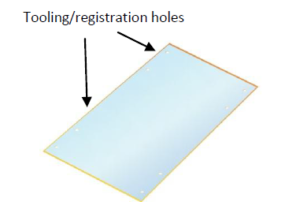 2. Drilling of Registration Holes. In order for the fabrication processes and the multiple layers within the heater to keep in alignment with one another, tooling holes are often drilled into the base laminate.
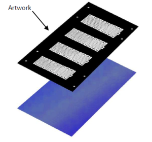 3. Imaging. This stage involves multiple process steps in order to create the pattern of the conductive element onto the base laminate. The first step is to laminate or coat a photo-imageable resist onto the panel. After that is complete with satisfactory adhesion, a high grade photo mask tool is placed over the resist. This mask has been generated from CAD design tools and represents the end-design of the heating element, including the applicable element width needed to produce the correct resistance of the heater.
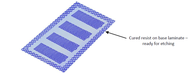
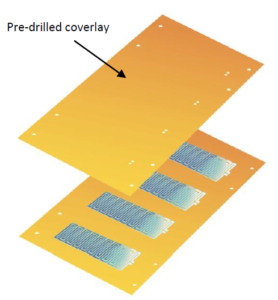 5. Top Dielectric Lamination. The next process sequence is to apply a top dielectric (coverlay) to the panel. This top film, also a polyimide, has a high-performance adhesive coating on one side. Prior to laminating the coverlay, the film is drilled in a correlating pattern to match the heater pattern and tooling holes in the base laminate. Access openings to the heating element are provided by this coverlay, including openings where wires and components are attached.
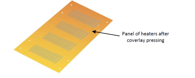
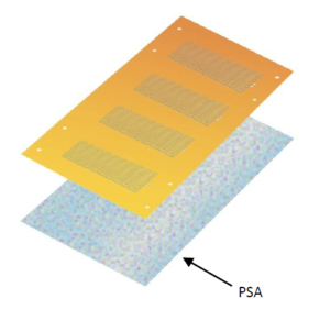 6. Optional Back Side PSA. If the customer desires, at this stage, pressure sensitive adhesive (PSA) is placed onto the rear surface of the panel. The PSA may be pre-cut to different shapes so that portions of the PSA are not on areas of the heater that the customer specifies.
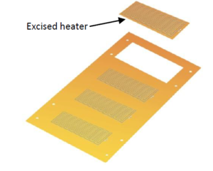 Tolerances and capabilities of steel rule dies are taken into account during the design phase but general variation in cutline dimensions are specified at +/-.010”.
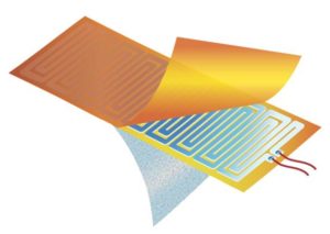
 customer service1