
|
Transparent heaters are widely used in technologies such as window defrosting/defogging, displays, gas sensing, and medical equipment. Apart from mechanical robustness and electrical and optical reliabilities, outstanding chemical stability is also critical to the application of transparent heaters. In this regard, we first present a highly flexible and large-area CuS transparent heater fabricated by a colloidal crackle pattern method with an optimized sheet resistance (Rs) as low as 21.5 Ω sq−1 at a ∼80% transmittance. The CuS transparent heater exhibits remarkable mechanical robustness during bending tests as well as high chemical stability against acid and alkali environments. In the application as a transparent heater, the CuS heater demonstrates a high thermal resistance of 197 °C W−1 cm2 with a fast switching time (<30 s), requiring low input voltages (<4.5 V) to achieve uniform temperatures of ∼110 °C across large areas. The temperature of the wearable CuS heater, which is stuck on the skin, can be real-time controlled through a Bluetooth device in a cell phone wirelessly. Based on the wireless control system, we demonstrated an application of the CuS heater in snow removal for solar panels. These CuS network TCEs with high flexibility, transparency, conductivity, and chemical stability could be widely used in wearable electronic products
The highly transparent, conductive, and environment-friendly humanhair-based NFs (nanofibers) was demonstrated using natural resources consisting of keratin, and the high-performance, flexible, transparent heaters based on the Ag NWs(nanowires)/NFs was successfully fabricated. With uniform coating with the conductive Ag NW nanomaterial, the as-prepared Ag NW networks on transparent NFs had a maximum optical transparency of 89% and sheet resistanceof 25 Ohm/square. In addition, the electrical stability of the Ag NWs/NFs after bending maintained almost the same value as that of the device before bending and was stable during repetitive mechanical bending of the Ag NWs/NFs. The temperature response and heat distribution results showed that the performance of Ag NW/NF based heaters is superior to that of conventional ITO-basedtransparent heaters and graphene-based heaters. The results of our study demonstrated that the Ag NWs/NFs possessed superior electrical conductance athigh optical transmittance with superior mechanical, electrical and thermal stabilities and can be used to produce an environment friendly and transparent conductive heater for future wearable electronic applications.
Fullchance is the leading manufacturer of glass heaters for the flat panel display industry. Typically, heaters are I.M.ITO™ to epoxy or air, for stand alone or lamination versions. The heater designed for 0.1 Watt/Sq. Inch – 5 Watt/Sq. Inch.
Fullchance has developed a unique software process to predict heat dissipation, power loading and temperature rise, in different sets of environments, for ruggedization.
Product Dimensions
Ion Beam Sputtering (Superior Process)
Applications:
Coating Non-Uniformity
BusBars: Surface Quality:
Durability: Packaging:
Custom Power Dissipation
Optical Characteristics (See Curves)
Other Material Resistivity Table
Resist Equation
For the final manufacture of a heater, the resistance for the heater (ohms) is converted to resistivity (*ohms/sq.) This value is a function of the length of the heater (L) and the width (W) as it relates to the total resistance. L is the size between bus bars.
p(Resistivity) Ohms S/SQ. = R (Resistance) Total in Ohms x (B + L)
The Heater consumes power per Ohms Law: P= E2 + R
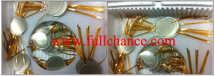
BusBar Coatings
Fullchance offers several solutions of low profile, solid state and silver bus bars completely compatible for all solvents and pull tests of 8K gram/sq in.
A. Metalized Busbar. Cr / Ni / Au Solderable
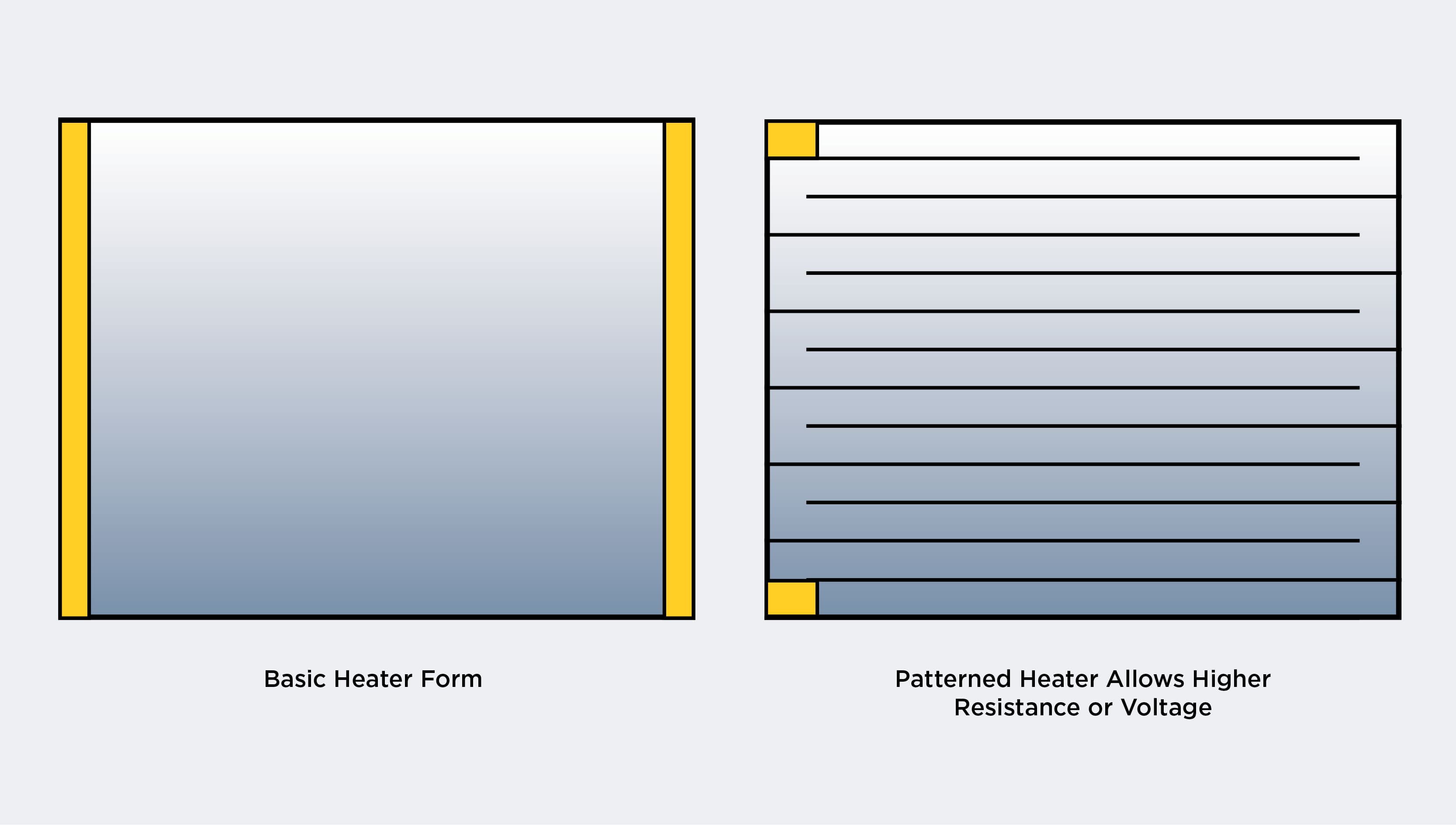
B. Silver Epoxy C. Copper Tape 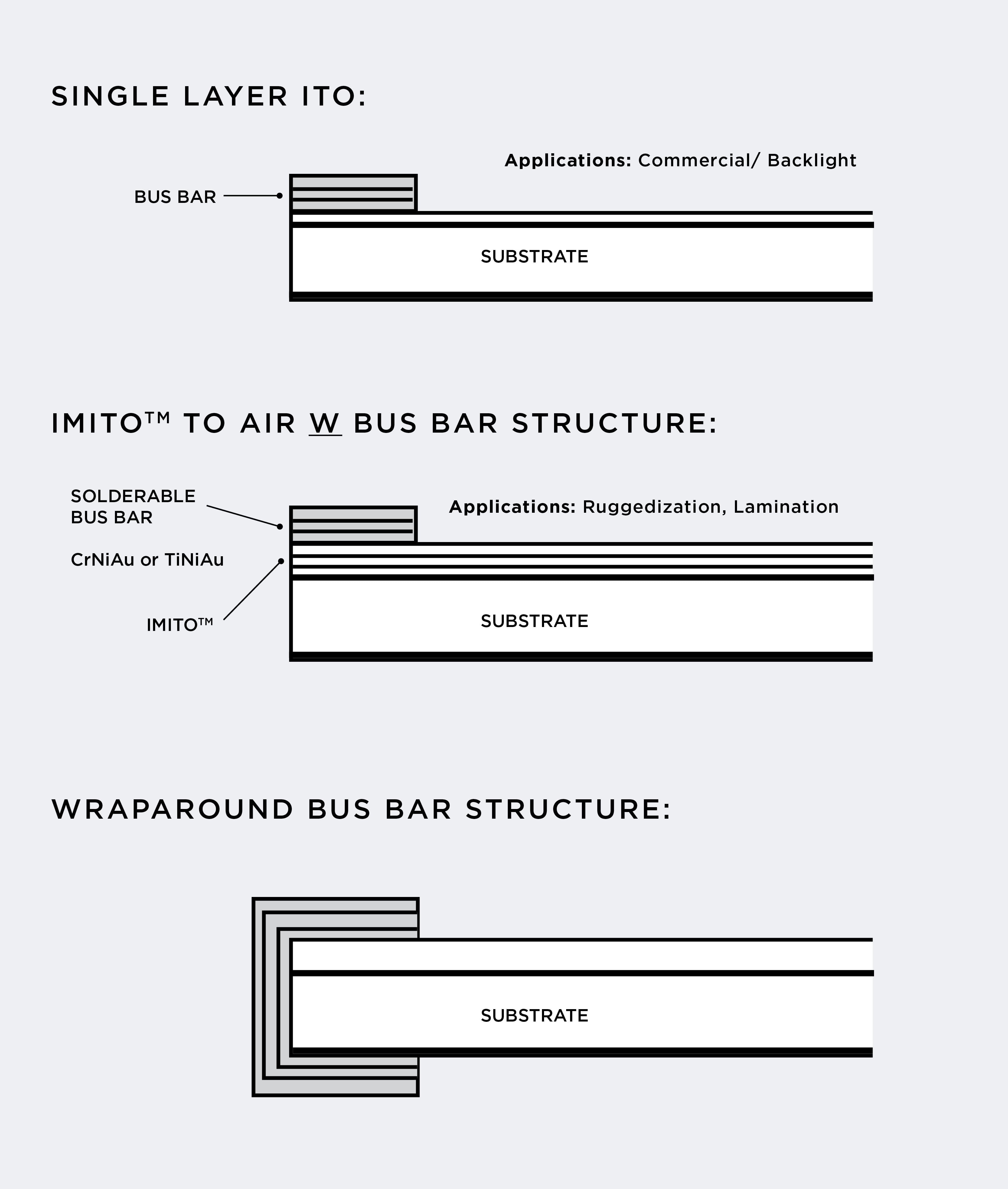 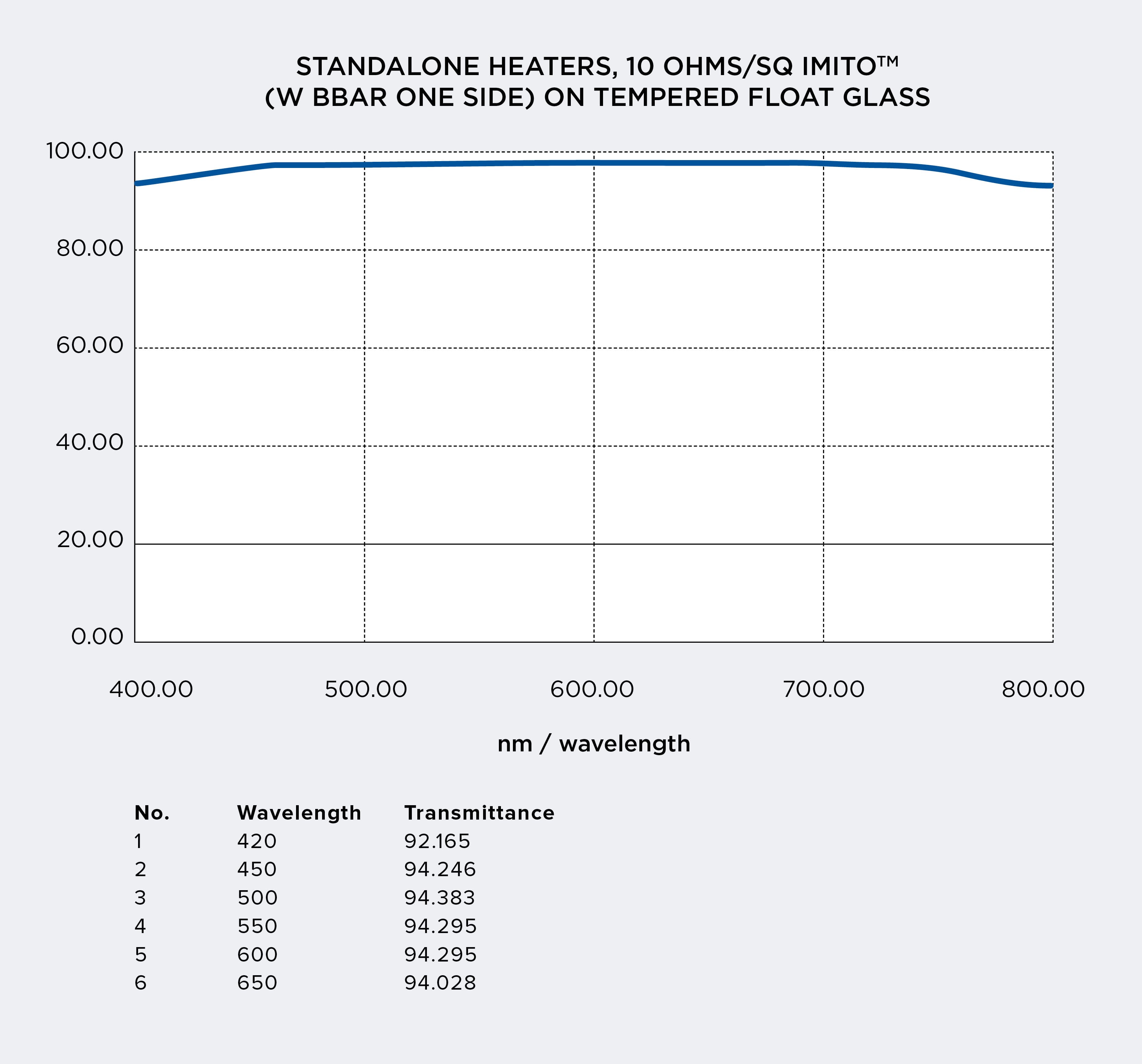 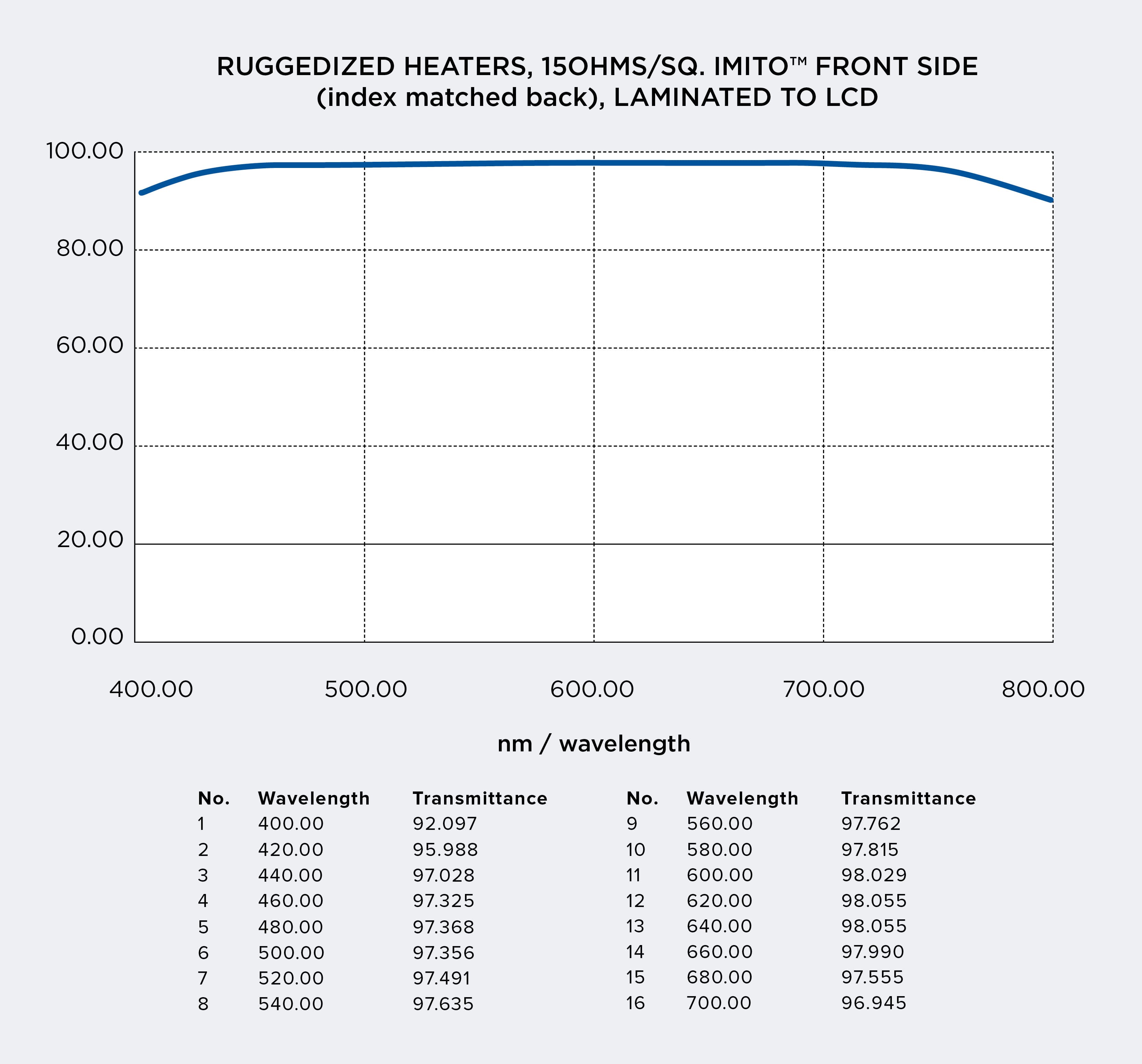 Transparent heaters are essential to use for challenging environments for cameras, LCD’s & electro-optical devices below -10ºC. The application in Avionics, cameras, LCD’s & locomotives require heaters so they can operate in cold and severe climates. Applying a heater is the simplest solution. The transparent heater is usually made by only I.T.O. or I.M.I.T.O. ™ with higher transmittance. The resistance of the heater determines the rate of heat required and power utilization. The lower the resistance, it requires higher power and higher rates of heating. Fullchance, Inc. has pioneered the use of I.T.O. and I.M.ITO ™ with BBAR coatings for efficient and high performance heaters for avionics, locomotives, flat panel displays, ships and cameras. The heating uniformity and burned out is controlled by very low resistive bus bar material with low contact resistance. The heaters can be designed for wide resistance from 300 – 5 ohms and voltages (115, 28, 24, 12 volt). The heater with I.T.O. or I.M.ITO ™ has been tested up to 10 watts per square inch. Usually a much lower heat is used for LCD display applications. The bonded heaters require less power than stand alone, typically 1/3. The I.T.O. and I.M.ITO ™ coatings are extremely reliable and stable for continuous operations. The typical visible transparency for I.T.O. is ≥ 80% avg., and IMITO™ is ≥ 92% average. The patterned heaters are commonly used for uniquely higher or lower powers, ≥ 10 watts/sq. inch. Fullchance can design patterned for various shapes, & sizes while maintaining uniform heating.
The patterned heaters are also very desirable for Infra-Red (IR) applications for wavelengths of 1.0 µm – 12 µm. Connection: Bus bar to heating surface. The contact resistance from the bus bar to the heating surface, I.T.O., I.M.I.T.O. ™, or NiCr must have ≤ 0.1 ohm. The other rule of thumb is to have individual bus bar resistance to be ≤ 5% of the total resistance of the heater. The bus bar materials are: A. Silver Epoxy B. Soldered Metallization C. Silver Frit Material The Silver Epoxy is inexpensive and decays in 2 – 3 years. The Silver Frit Material has to be fired at ≥ 350°C which deforms glass flatness and this process contaminates the surface. The Metalized Bus bar, such as Cr/Ni/Au, is a solid state process and works extremely well with Soldered bus bar heaters. This is a highly recommended process. (See Heaters – 1 Page).
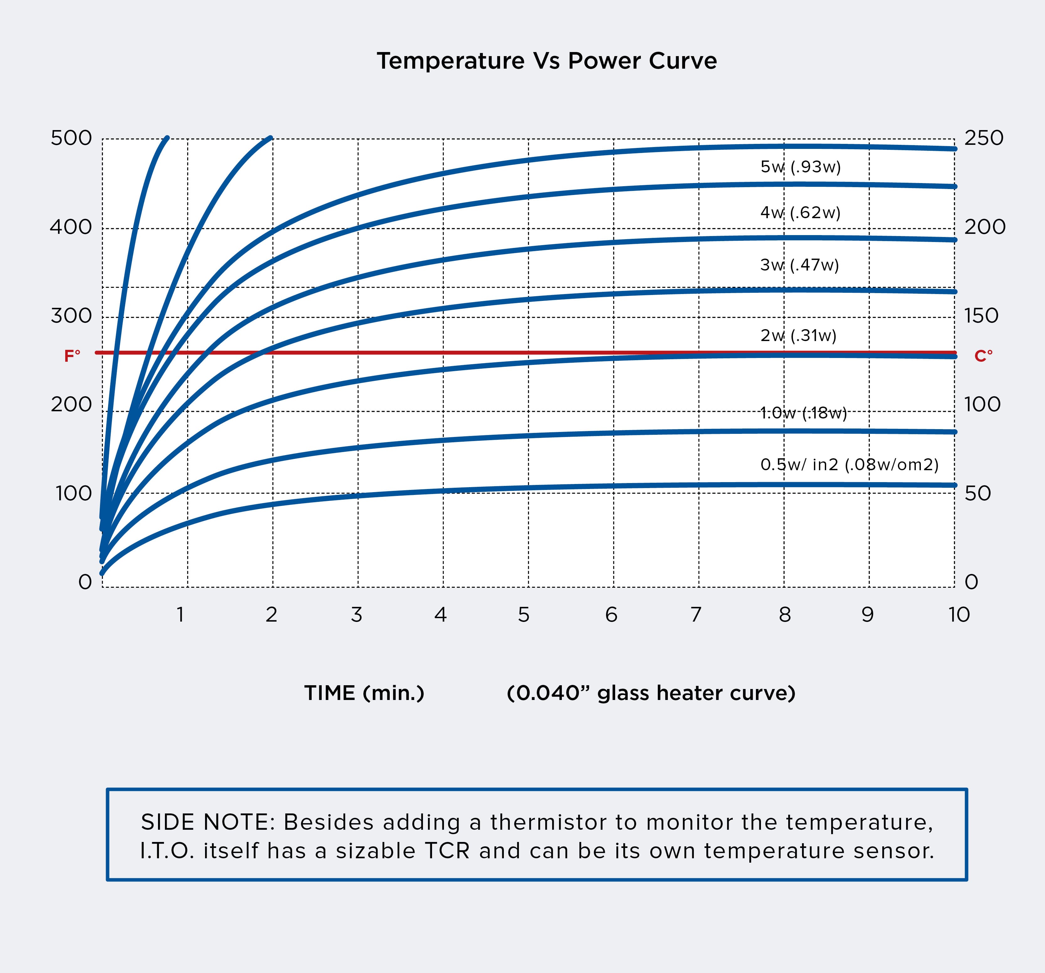
Power Calculation: Below a Temperature Rise curve is provided that gives the relationship of time versus power of the heater with thickness 0.040”. There are different ways to apply heater glass with displays: A. Stand alone. B. Laminated. The standalone are typically applied in the back of the displays and have air gaps, 0.008” – 0.020”, which makes it a poor heating system. For low heat requirements it’s plenty. For fast rise temperature the heater glass should be bonded for optimum avionics applications. Mounting heater glass on the front (viewing side) of the display is not recommended as heat loss to air could be as high as 50% of the total heat. A thermistor or I.T.O. / Thermal coefficient of resistance (TCR) is commonly used to control temperature.
If higher temperatures are used to quickly heat the display, you must reduce that heat level once at operating temperature. Additionally, it is not recommended to operate heaters above a 20°C ambient temperature.
Resistivity Table
BusBar Materials as Follows
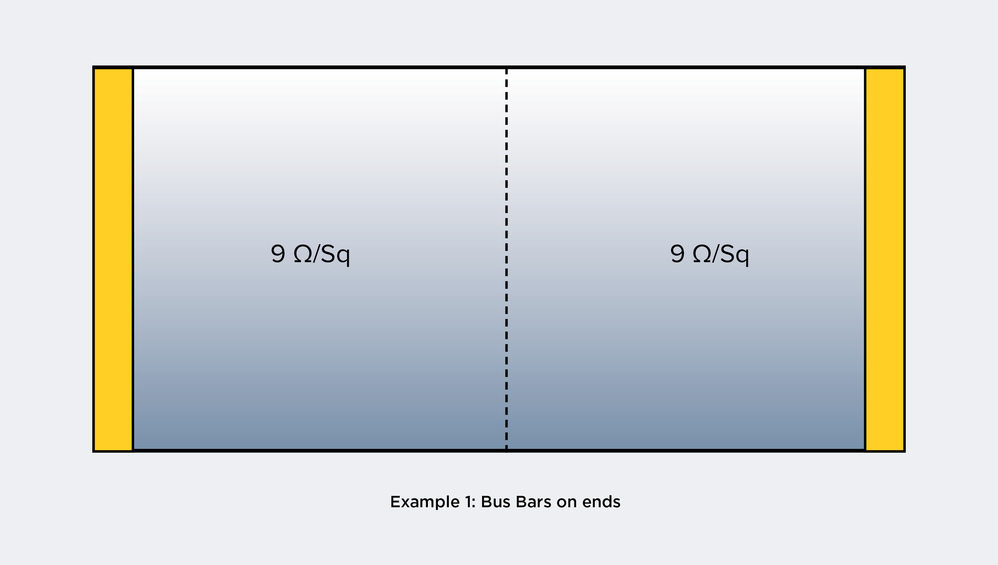 To complete the Example, we’ll use 6 Volts to power the heater. So, R becomes 18 ohms (6, squared, divided by 2). Now the heater resistance and part sizes are all that’s required to define a heater to Fullchance; But there, heater resistance is converted into resistivity for production purposes. Resistivity is the surface resistance nature the manufacturer coats so the part shows the correct resistance. To determine the resistivity value, it’s calculated with the length (L) and width (W). (Note: Length is always the distance between bus bars, even if smaller than the width).
Process: Sputtering Heater Coating Materials: The most commonly used transparent resistive coatings are I.T.O. (Indium Tin Oxide), and tin oxide. Fullchance concentrates on producing superb quality I.T.O. and IMITO™, in a variety of forms. Opaque conductor films are Aluminum, Nichrome, Inconel, Tantalum, Nitride and cermet films. Substrate materials can be glass, quartz, ceramic, plastic, kapton, polyester and others. |
- Home
- Silicone Heater
Foam insulation silicone heater
Silicone heater with temperature controller
SILICONE RUBBER HEATERS – ACCESSORIES
Silicone Heater for Small Diameter Pipes and Tubing
special shaped silicone rubber heater
Different color silicone heater
Type W / Type E Silicone Rubber Heate
features&application of wire wound silicone heater
Standard silicon rubber heater
Silicone band Heater With Springs
Silicone Drum Heater With Velcro Straps
Silicone Drum Heater With Temperature Controller
Silicone Rubber Heater Temperature Controls
Useful information for designing silicone heaters
- Thick Film Heater
what are ceramic based thick film heaters,resistors,circuits of devices
Is thick film right for my applications
what base or substrate materials are available
what are the benefits of thick film heaters
which substrate materials should use?
what termination options are available?
what are the wattage densities of the thick film conduction heaters
waht if a standard thick film heater is close but not perfect for my applications
AVIATION LATCH HEATER(thick film on ceramic
2-ZONE HEATER FOR HANDHELD ANALYTIC DEVICE
DEVICE HEATING ELEMENT FOR USE IN A HIGHLY SENSITIVE MAGNETOMETER
- Polyester heater
- Epoxy Resin Heater
- Kapton heater
- Mica Heater
Mica HeaterUltra-thin・high Watt precision heater
High Frequency Round Mica Plate Heater Customized
High Temperature Surface Mica Heating Element
High Reliability Mica Heater Plate , Mica Electric Heaters Multi Function
The electric film mica heating element introduced
Mica Panel Heater/Heating Element
- Ceramic Heater
Alumina metallic ceramic heating element
Rectangular alumina metallic ceramic heating element specification
Round shape alumina metallic ceramic heating element specifications
Rod shape alumina metallic ceramic heating element specifications
4mm alumina ceramic porous wick for electronic cigarette
5W Ceramic Heater Element for Car Sensor 12V
MCH Printing Porous Ceramic Heating Element for Electric Cigarette
Electroniccigarette ceramic heater
Pellet System Applications Igniters
- Transparent Heater
Transparent Heater utilizes ITO technology
transparent heater custom&design
Transparent Heater with Nanofibrous Membranes
stretchable transparent heater
Clear Heater (ITO Heater), Anti-fog Heater, ITO film Heater, Film Heater, Transparent Heater
Clear Heater (ITO Heater for LCD display
Clear Heater (ITO Heater), Anti-fog Heater for TP 8 inch LCD display
ITO film Heater, Film Heater, Transparent Heater
- News
How to Install a Silicone Heater Build Plate
How a Silicone Heating Pad Works
Types of Flexible Silicone Rubber Heaters
Why Use Silicone rubber Heaters Over Other Heaters?
5 Advantages of silicone rubber heaters
Everything you ever wanted to know about Kapton heaters but were afraid to ask
what is ELECTRICALLY HEATED SILICONE BLANKETS
What Are Flexible Printed Heaters?
how to test kapton heater with Lithium Polymer (LiPo) battery
application of polyimide kapton heater
3D Printing Custom heaters for additive manufacturing and 3D printing
How do Polyimide Heaters Work?
What are the Operating Temperatures of Polyimide Heaters?
What are the Applications of a Polyimide Heater?
max working temperature of Polyimide Heater
How Does A Micathermic Space Heater Work Faster Than Regular Heaters
Are Mica Panel Heaters Safe and Effective?
From consulting and design services to product manufacturing
Things to Consider When Specifying a Heating Application
Kapton Flexible Heaters - Flexible Heating Solutions
Thick film elements - Technical data
How do I estimate battery run-time for my heated device?
Understanding Watt Density in Heater Design
latest product-230V 1.2W 50000ohms carbon heater
what is etched-foil kapton heaters
ITO conductive glass and related transparent conductive films
- Data Download
Fullchance FILM HEATERTEST WITH SINK
Electric heating film product catalog
Ceramic electric heating tube product catalog
ITO conductive glass and related transparent conductive films
Transparent electric heating film video
PI High Temperature Electric Heating Plate Test Video 300 degrees
Transparent electric heating film inspection report
General testing standard for mica electric heating plates
Hot stamping machine, baking cup heating pad information download
Electric Heating Production Operation Instructions
Electric heating film, flexible heating film test report
Operating Procedures for Electric Heating Plate Production
Analysis of Electric Heating Plate Mechanism
Test Report on Kapton (PI) Insulation Layer for Electronic Cigarette
Temperature Uniformity Test Video for Epoxy Resin Electric Heating Plate
Production process and process flowchart of electric heating film
Instructions for Inspection of Mica Heating Plate
Technical description of ITO transparent electric heating pads for ski goggles and helmets
- Company Profile
- Factory Equipment
Electric heating film application - medical diagnostic equipment
Electric Heating Film Application - Aviation
Application of Electric Heating Film - National Defense
Electric Heating Film Application - Engineering Automation
Electric heating film application - power generation
Electric Heating Film Application - Rotating Machinery
Electric heating film application - semiconductor manufacturing
Electric Heating Film Applications - Industrial&Commercial Applications
Installation drawing of CT325 temperature controller
CT435 Temperature Control Installation Drawing
Installation Drawing of CT425 PID Temperature Control System
- Contact Us
 customer service1