

The refractive index of the ITO conductive layer is approximately 1.9‑2.1, that of the glass substrate is about 1.52, and the refractive index of air is 1.0. Mismatched refractive indices at the interfaces cause 8%‑12% surface reflection, which results in screen glare and reduced light transmittance.
For ITO electric‑heated glass, it is required to maintain conductive heating as well as defogging and defrosting performances, while reducing reflection and improving light transmittance. Therefore, an anti‑reflection (AR) coating shall be designed on the ITO conductive surface. Design constraints: the conductive performance of ITO shall not be impaired, and the sheet resistance and heating power shall not degrade significantly.
Central reference wavelength: 550 nm (green light in visible spectrum, a commonly‑used waveband for optical lenses and instrument windows).
Basic Principles
Based on the thin‑film optical destructive interference principle, the film thickness (λ/4, λ/2) of multi‑layer films is precisely controlled to counteract reflected light from different interfaces, so as to reduce surface reflection and improve overall transmittance.
V‑type double‑layer coating: achieves anti‑reflection only near a single wavelength, suitable for narrow‑band applications.
W‑type double‑layer coating: features two reflection minimum points to broaden the working spectrum.
Multi‑layer AR coating: provides broadband anti‑reflection across the full visible range of 400‑700 nm, and is the preferred option for industrial optical windows.
Key Design Constraints (Specific to ITO‑Heated Glass)
Priority on Electrical Conductivity
The anti‑reflection coating is deposited on top of ITO. It must not penetrate into the ITO layer or increase sheet resistance. The coating thickness shall not be excessive to prevent poor electrode contact.
Temperature Resistance
The maximum operating temperature of the product is 120‑130℃. The coated layer shall feature high‑temperature resistance and matched thermal expansion, without cracking or peeling under high‑temperature conditions.
Environmental Reliability
The coating shall resist humidity and moisture. For bathroom and outdoor equipment, SiO₂ is preferred as the outermost layer, while MgF₂ exhibits weak moisture‑proof performance.
Wavelength Band Confirmation
Whether the customer‑applied wavelength band is visible light (400‑700 nm) or a specific single wavelength directly determines the selection of film system.
Substrate Limitations
Flat glass is suitable for vacuum sputtering coating. Coating on curved glass becomes more difficult, and film‑thickness uniformity shall be evaluated.
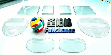
Reference Technical Specifications (Fullchance ITO Electric‑Heated Glass with AR Anti‑Reflection Coating)
Operating Wavelength Band: 400‑700 nm visible light
At 550 nm: Surface reflectance ≤2%
Overall Light Transmittance: ≥82%‑88% (depending on ITO sheet resistance)
Sheet Resistance: Maintain the original ITO design value; sheet resistance variation after coating ≤5%
Maximum Operating Temperature: 120‑130℃
Coating Adhesion: No peeling after cross‑hatch test
Parameters to Be Provided by Customers for Model Selection
1.Glass dimension and thickness; flat / curved surface
2.Target ITO sheet resistance (determines heating power)
3.Spectral band to be optimized
4.Required indicators for reflectance and light transmittance
5.Service environment: humidity, temperature, outdoor / indoor
6.Requirements for friction resistance and moisture resistance or not
 customer service1