

1 Direct Wafer Bonding
2 Anodic Wafer Bonding
3 Wafer Adhesion
4 Glass Frit Wafer Bonding
5 Eutectic Wafer Bonding
6 Transient Liquid Phase (TLP) Wafer Bonding
7 Metal Thermocompression Wafer Bonding
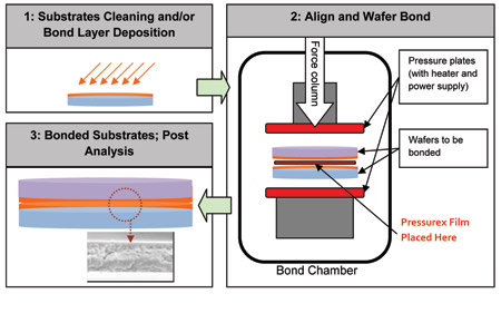
1. Direct Wafer Bonding
• This is a wafer bonding method in which adhesion between two surfaces occurs due to chemical bonds established between molecules
of the two surfaces.
of the two surfaces.
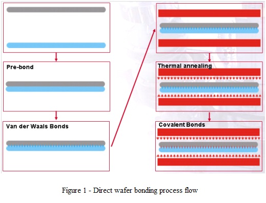
• Typically, the adhesive force at room temperature is weak (mediated by van der Waals forces). High‑temperature thermal annealing converts
weak bonds into covalent bonds to achieve maximum bonding strength (the process flow is shown in Figure 1).
weak bonds into covalent bonds to achieve maximum bonding strength (the process flow is shown in Figure 1).
For Si‑Si direct bonding, the annealing temperature for hydrophobic bonding is >600°C (1‑2% HF is used to remove SiO₂ from Si prior to
bonding), while the annealing temperature for hydrophilic bonding is >900°C (native, thermally‑grown or deposited oxides are used). After proper
thermal annealing, the bonding strength reaches the same range as the bulk silicon fracture strength.
bonding), while the annealing temperature for hydrophilic bonding is >900°C (native, thermally‑grown or deposited oxides are used). After proper
thermal annealing, the bonding strength reaches the same range as the bulk silicon fracture strength.
• Surface‑activated wafer bonding is also a direct bonding method. It adopts a special surface treatment process (surface activation) to modify and
control the bonding mechanism by regulating surface chemistry.
control the bonding mechanism by regulating surface chemistry.
• After surface activation, higher‑energy bonds (even covalent bonds) are formed at room temperature compared with non‑activated surfaces. Accordingly,
less energy is required to achieve maximum bonding strength by forming covalent bonds across the entire bonding interface.
less energy is required to achieve maximum bonding strength by forming covalent bonds across the entire bonding interface.
• Therefore, the annealing temperature and annealing time for this scenario are much lower than those of standard direct bonding processes. The annealing
temperature range for such processes is from room temperature to 400°C, depending on the materials to be bonded. A typical surface activation applied
in this process is plasma activation performed with the EVG®800 series plasma chamber for precise process control.
temperature range for such processes is from room temperature to 400°C, depending on the materials to be bonded. A typical surface activation applied
in this process is plasma activation performed with the EVG®800 series plasma chamber for precise process control.
• Typical materials for direct wafer bonding under various process conditions are:
◦ Silicon, silicon dioxide, quartz, fused silica glass, other glasses (e.g., borofloat, BK7, special‑performance glasses)
◦ Compound semiconductors (GaAs, InP, GaP, etc.)
◦ Oxide materials (LiNbO₃, LiTaO₃, etc.)
• The general requirement for direct bonding is a surface micro‑roughness of <0.5 nm (in some cases, higher values may be acceptable subject to process
condition boundaries).
condition boundaries).
◦ Micro‑roughness is commonly defined as the surface Rms measured by atomic force microscopy (AFM) over a 2 × 2 μm² area on the substrate.
Anode Wafer Bonding
Anode Wafer Bonding
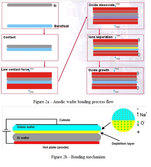
• The term "anodic bonding" was originally used to join metal surfaces to glass surfaces, and is now primarily used to refer to the bonding of silicon wafers to
glass wafers with a high alkali‑metal oxide content (Figure 2).
glass wafers with a high alkali‑metal oxide content (Figure 2).
The main glass materials used for anodic bonding are Borofloat from Schott Glass of Germany and Pyrex7740 from Corning Incorporated of the United
States.
States.
• Bonding occurs when two wafers are brought into contact, heated, and subjected to an electric field.
◦ At a certain temperature (depending on glass composition), oxides dissociate. Mobile alkali ions are driven into the glass by the electric field, forming an
oxygen‑rich layer at the silicon‑glass interface. Oxygen ions are driven to the silicon surface by the electric field and cause oxidation of silicon. The resulting
bond strength is extremely high, and the process is irreversible.
oxygen‑rich layer at the silicon‑glass interface. Oxygen ions are driven to the silicon surface by the electric field and cause oxidation of silicon. The resulting
bond strength is extremely high, and the process is irreversible.
• In terms of equipment, it is critical for the bonding chamber to deliver good temperature uniformity and ensure reliable electrical contact.
3. Wafer Bonding
• Wafer bonding is a bonding technology that employs an intermediate layer.
• Polymers, spin‑on glass, photoresists and polyimides are some materials suitable for use as bonding intermediate layers.
• The selection of intermediate‑layer materials must always take substrate materials and topography into consideration.
• The main advantages of this method are: low‑temperature processing (maximum temperature below 400°C), surface planarization, and particle tolerance
(the intermediate layer can accommodate particles with diameters within the layer thickness range).
4. Glass Frit Wafer Bonding
(the intermediate layer can accommodate particles with diameters within the layer thickness range).
4. Glass Frit Wafer Bonding
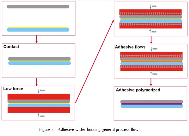
• This type of adhesive serves as an intermediate layer for bonding low‑melting‑point glass.
• Bonding is achieved by heating the substrates while applying contact force (Figure 4).
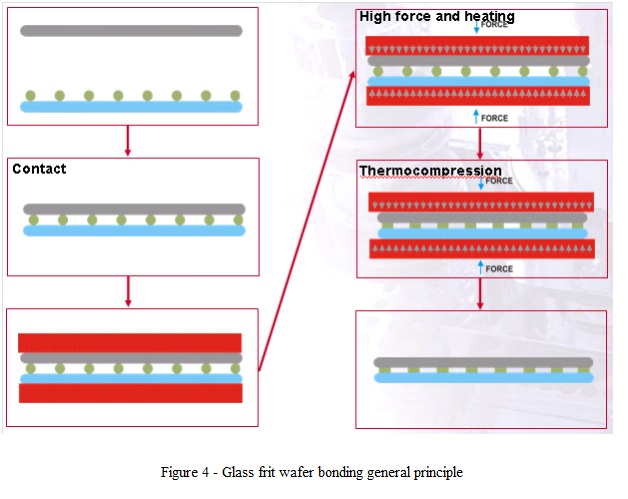
Glass frit bonding features high tolerance to surface roughness and is capable of conforming to the high topography of substrates.
Glass frit bonding features high tolerance to surface roughness and is capable of conforming to the high topography of substrates.
• Glass frit materials can be deposited via screen printing or used as glass preform sheets.
• This process is highly reliable and is adopted by major MEMS device manufacturers in mass‑production applications requiring low‑vacuum packaging.
5. Eutectic Wafer Bonding
• This is a type of wafer bonding process that uses a eutectic alloy formed during bonding as the bonding layer.
• The eutectic alloy forms at the bonding interface through a liquid‑phase process; therefore, compared with direct wafer bonding methods, eutectic bonding
is less sensitive to surface flatness irregularities, scratches and particles (the metal layer can accommodate particles with a diameter smaller than the thickness
of the eutectic layer).
is less sensitive to surface flatness irregularities, scratches and particles (the metal layer can accommodate particles with a diameter smaller than the thickness
of the eutectic layer).
• Table 1 lists several major eutectic alloys for wafer bonding applications.
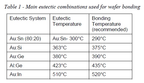
For a successful eutectic bonding process, it is critical for the bonder to ensure good temperature uniformity across the entire wafer surface and precise
temperature control (to avoid exceeding the set‑point) so as to achieve a reliable process.
For a successful eutectic bonding process, it is critical for the bonder to ensure good temperature uniformity across the entire wafer surface and precise
temperature control (to avoid exceeding the set‑point) so as to achieve a reliable process.
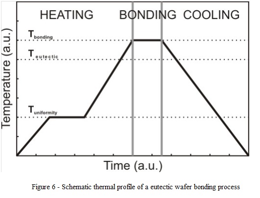
• Experimental results show that good‑quality interfaces can be obtained by raising the temperature to a value below the eutectic temperature (simultaneous heating
from top/bottom), holding it constant for a short period to achieve uniform heating of both wafers, then increasing the temperature again via the two heaters to 10‑20 °C
above the eutectic point (depending on specific process conditions and substrate constraints), followed by cooling down to a temperature below the eutectic temperature.
• A typical thermal profile for the eutectic wafer bonding process is shown in Figure 2.⁶
Eutectic wafer bonding does not require high contact force.
Eutectic wafer bonding does not require high contact force.
• Since a liquid phase is formed during the process, high contact force always causes metal to be squeezed out of the interface, resulting in poor uniformity
of the interface layer and contamination of the bonding tool and bonding chamber.
of the interface layer and contamination of the bonding tool and bonding chamber.
• The purpose of the slight contact force required is only to ensure good contact between the two wafers, as well as good contact between the two heaters of the
bonder and the backside of the wafers.
bonder and the backside of the wafers.
• Eutectic wafer bonding is an excellent choice for high‑vacuum applications, as this process uses only high‑purity components and therefore exhibits extremely
low specific outgassing.
low specific outgassing.
• The liquid melt formed during processing can only enhance high‑vacuum compatibility by achieving high‑quality sealing on imperfect surfaces.
6. Transient Liquid Phase (TLP) Wafer Bonding
• For certain applications, the process temperature must be lower than the bonding temperature of the most common eutectic alloys (300°C‑400°C).
• In such cases, alternative processes can be adopted to form an intermetallic‑compound bonding layer.
• This process is known by different names in literature, among which "diffusion welding" and transient liquid phase (TLP) bonding can be mentioned.
• This bonding process is an advanced solder bonding technique capable of forming high‑quality hermetic seals at lower temperatures than other bonding technologies.
• This technology employs a thin metal layer (typically 1‑10 μm thick) that diffuses into its bonding partner during heat treatment to form an intermetallic‑compound layer
whose remelting temperature is higher than the bonding temperature (Table 2). The process flow and recommended thermal profile are identical to those for eutectic wafer
bonding (Figure 6).
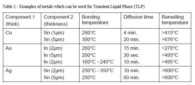
This table is adapted from [G. Humpston and D. Jacobson, *Principles of Welding*, ASM International, 2004, p.14.231]. The times correspond to complete diffusion through
the specified thickness of component 2.
whose remelting temperature is higher than the bonding temperature (Table 2). The process flow and recommended thermal profile are identical to those for eutectic wafer
bonding (Figure 6).
This table is adapted from [G. Humpston and D. Jacobson, *Principles of Welding*, ASM International, 2004, p.14.231]. The times correspond to complete diffusion through
the specified thickness of component 2.
• Like eutectic wafer bonding, diffusion welding bonding is attractive for MEMS vacuum packaging, as the process is completed at low temperatures (150°C‑300°C) and can
withstand higher temperatures after bonding (see Table 2). The bonding layers are made of metals (low permeability), and they can planarize surface defects or particles
generated by prior processes.
withstand higher temperatures after bonding (see Table 2). The bonding layers are made of metals (low permeability), and they can planarize surface defects or particles
generated by prior processes.
7. Metal Thermocompression Wafer Bonding
• It is often mistakenly believed that thermocompression bonding and eutectic bonding are a single process.
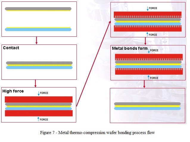
• During thermocompression bonding, the two surfaces adhere to each other as metallic bonding is established between the two metal surfaces pressed together under heating.
• The bonding mechanism is enhanced by deformation of the two contacting surfaces to break any intervening surface films and achieve metal‑to‑metal contact (Figure 7).
• By heating the two metal surfaces, the contact force applied during the bonding process can be minimized. Force uniformity across the entire bonding area is high, thus enabling
high yield.
Multiple metals are used for metal thermocompression bonding, such as gold, copper, or aluminium.
high yield.
Multiple metals are used for metal thermocompression bonding, such as gold, copper, or aluminium.
• These are considered interesting for wafer‑bonded MEMS applications, mainly due to their availability in major microelectronics applications.
• Their use for one type of application or another depends on the type of substrate employed (for example, gold‑containing substrates cannot be further processed in CMOS
production lines).
production lines).
• Typically, the metals used for this process are evaporated, sputtered, or electroplated onto the surface. In such processes, it is extremely important to ensure a proper diffusion
barrier or adhesion layer exists between the metallic bonding layer and its substrate.
barrier or adhesion layer exists between the metallic bonding layer and its substrate.
• The surface micro‑roughness of metallic bonding layers ranges from <1 nm up to several tens of nanometers, depending on the metal used, deposition technique, and wafer
bonding process conditions.
bonding process conditions.
 customer service1